电 话: +86 515-87237339
+86 515-87236996
传 真: +86 515-87236996
联系人: 王祥生
手 机: +86 13770162899
客服QQ: 475061838
邮 箱: 475061838@qq.com
xsy2899@gmail.com
WhatsApp:+44 7536286442
地 址: 阜宁经济开发区华山路31号
网 址: www.xsyfm.com

产品说明:
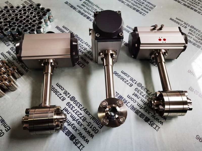
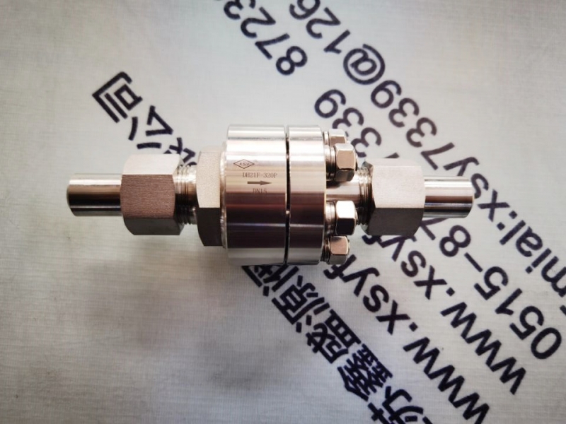
H42W立式止回阀正常处于关闭状态,由于管线中进口端介质的压力作用,而克服弹簧阻力使阀门开启。当进口端介质压力低于出口端时,弹簧将阀芯推向阀座而使阀门关闭,阻止介质逆流,故起止回作用。
本阀门由于采用弹簧支撑阀芯,故采用立式安装或卧式装均可。
产品名称:旋启式止回阀,升降式止回阀
产品型号:H44,H41
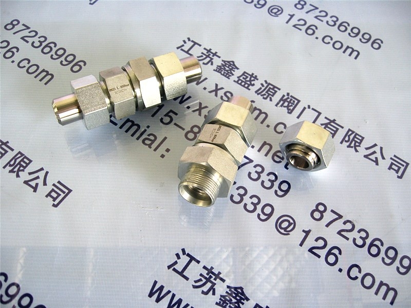
连接方式:螺纹 卡套 焊接 法兰
压力等级:1.0MPa~ 16.0MPa
产品规格:DN10 ~ 350mm
产品材质:WCB碳钢,不锈钢,铬钼钢等等
适用温度:≤425 ℃
适用介质:水、石油、天然气等
主要外形尺寸和连接尺寸:
| 型号 | 公称通径 DN(mm) | 尺寸(mm) | ||||||||
| L | D | D1 | D2 | b | f | Z-Φ | ||||
| 1 | 2 | 3 | ||||||||
| H42W-25P H42W-25R | 15 | - | 85 | 85 | 95 | 65 | 45 | 16 | - | 4-Φ14 |
| 20 | - | 95 | 95 | 105 | 75 | 55 | 16 | - | 4-Φ14 | |
| 25 | - | 100 | 105 | 115 | 85 | 65 | 16 | - | 4-Φ14 | |
| 32 | - | 105 | 150 | 135 | 100 | 78 | 16 | - | 4-Φ14 | |
| 40 | - | 115 | 160 | 145 | 110 | 88 | 18 | - | 4-Φ14 | |
| 50 | 140 | 125 | 170 | 160 | 125 | 100 | 20 | 3 | 4-Φ14 | |
| 65 | 160 | 145 | 180 | 180 | 145 | 120 | 22 | 3 | 8-Φ18 | |
| 80 | 185 | 155 | 200 | 195 | 160 | 135 | 22 | 3 | 8-Φ18 | |
| 100 | 210 | 210 | 210 | 230 | 190 | 160 | 24 | 3 | 8-Φ23 | |
| 125 | - | 275 | 275 | 275 | 220 | 188 | 28 | 3 | 8-Φ25 | |
| 150 | 300 | 225 | 300 | 300 | 250 | 218 | 30 | 3 | 8-Φ25 | |
| 200 | 380 | 380 | 380 | 360 | 310 | 278 | 34 | 3 | 12-Φ25 | |
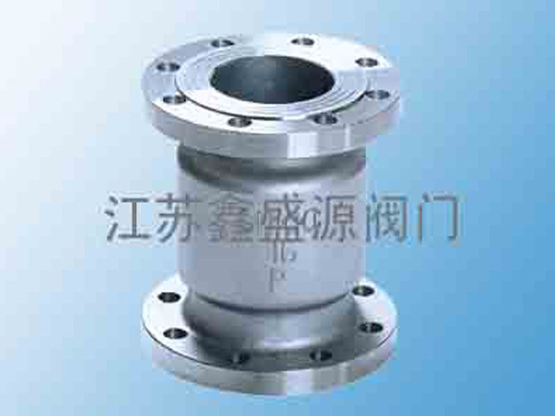
H42W立式止回阀
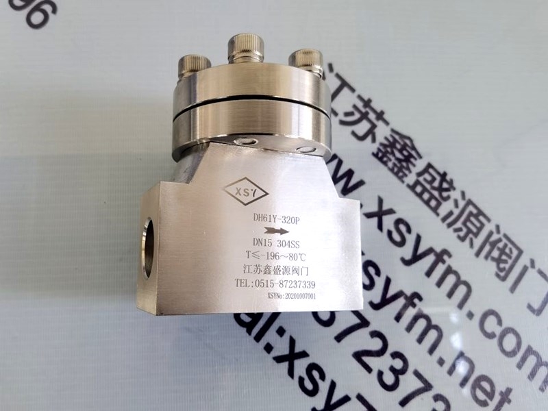
H42W立式止回阀是一种法兰连接的升降立式止回阀。它属于自动阀门,其作用是防止管道中的介质倒流,确保介质向一个方向流动,以避免发生事故。该产品严格按GB12235标准设计制造,阀瓣沿着中心定位作升降运动。它广泛应用于石油、化工、制药、电力行业等各种工况的管路上。
H42W立式止回阀主要特点
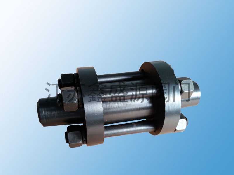
· 结构紧凑:具有结构简单,零部件少,重量轻等特点。
· 动作稳定:衬套采用耐磨性能好、摩擦系数小的特殊材料制作,动作灵活可信,密封性能优良。
· 安装便利:主要用于垂直管道安装。用于立式安装时,通常可不设弹簧,利用阀瓣自身的重量及流体回流的压力起止回作用。
H42W立式止回阀主要技术参数
主要性能规范
下表汇总了该阀门的主要性能规范:
型号 Model 公称压力 Nominal Pressure PN(MPa) 试验压力 Test Pressure Ps (MPa) 适用温度 Applicable Temp. (℃) 适用介质 Applicable Media
壳体 Shell Test 密封 Seal Test
H42W-16C 1.6 2.4 1.76 ≤425
H42W-16P 1.6 2.4 1.76 ≤200
H42W-25P 2.5 3.75 2.75 ≤200
H42W-25R 2.5 3.75 2.75 ≤200
H42W-40P 4.0 6.0 4.4 ≤200
H42W-40R 4.0 6.0 4.4 ≤200
H42Y-40 4.0 6.0 4.4 ≤425
H42W立式止回阀主要零件材料
下表为主要零件材质信息:
零件名称 Part Name H42W-16C H42W-16P / 25P / 40P H42W-25R / 40R H42Y-40
阀体、阀瓣 Body, Disc 碳钢 Carbon Steel 铬镍钛不锈钢 Stainless Steel (Cr-Ni-Ti) 铬镍钼钛不锈钢 Stainless Steel (Cr-Ni-Mo-Ti) 碳钢 Carbon Steel
导向阀 Guide 碳钢 Carbon Steel 铬镍钛不锈钢 Stainless Steel (Cr-Ni-Ti) 铬镍钼钛不锈钢 Stainless Steel (Cr-Ni-Mo-Ti) 碳钢 Carbon Steel
H42W立式止回阀密封面 Sealing Surface 碳钢 Carbon Steel 铬镍钛不锈钢 Stainless Steel (Cr-Ni-Ti) 铬镍钼钛不锈钢 Stainless Steel (Cr-Ni-Mo-Ti) 堆焊硬质合金 Hard-faced Alloy
H42W立式止回阀主要外形连接尺寸
以下是部分常见通径的尺寸参考(单位:mm):
公称通径 Nominal Diameter DN L D D1 D2 b f Z-Φd
25 115 115 85 65 16 2 4-Φ14
32 120 135 100 78 18 3 4-Φ18
40 130 145 110 85 18 3 4-Φ18
50 140 160 125 100 20 3 4-Φ18
65 160 180 145 120 22 3 8-Φ18
80 185 195 160 135 22 3 8-Φ18
100 210 230 190 160 24 3 8-Φ23
125 250 270 220 168 28 3 8-Φ25
150 300 300 250 218 30 3 8-Φ25
200 380 360 310 278 34 3 12-Φ25
Product Overview: H42W Vertical Lift Check Valve
Product Definition & Application
The H42W Vertical Lift Check Valve is aflanged vertical lift check valve . It is an automatic valve designed to prevent the backflow of medium in pipeline systems, ensuring one-way flow to avoid accidents . This product is strictly designed manufactured according to the GB12235 standard , with the disc moving up down along the central guide . It is widely used in pipelines across industries such as petroleum, chemical, pharmaceutical, power generation .
Key Features
· Compact Structure: It features a simple structure, few parts, light weight .
· Reliable Operation: The bushing is made of special material with good wear resistance a low friction coefficient, ensuring flexible reliable operation excellent sealing performance .
· Easy Installation: It is primarily designed for installation in vertical pipelines . When installed vertically, it generally operates without a spring, relying on the weight of the disc itself the pressure of the reverse fluid to perform the check function .
Main Technical Parameters
Main Performance Specifications
The table below summarizes the main performance specifications:
Model Nominal Pressure PN(MPa) Test Pressure Ps (MPa) Applicable Temp. (℃) Applicable Media
Shell Test Seal Test
H42W-16C 1.6 2.4 1.76 ≤425
H42W-16P 1.6 2.4 1.76 ≤200
H42W-25P 2.5 3.75 2.75 ≤200
H42W-25R 2.5 3.75 2.75 ≤200
H42W-40P 4.0 6.0 4.4 ≤200
H42W-40R 4.0 6.0 4.4 ≤200
H42Y-40 4.0 6.0 4.4 ≤425
Main Part Materials
The following table provides information on the main part materials:
Part Name H42W-16C H42W-16P / 25P / 40P H42W-25R / 40R H42Y-40
Body, Disc Carbon Steel Stainless Steel (Cr-Ni-Ti) Stainless Steel (Cr-Ni-Mo-Ti) Carbon Steel
Guide Carbon Steel Stainless Steel (Cr-Ni-Ti) Stainless Steel (Cr-Ni-Mo-Ti) Carbon Steel
Sealing Surface Carbon Steel Stainless Steel (Cr-Ni-Ti) Stainless Steel (Cr-Ni-Mo-Ti) Hard-faced Alloy
Main Face-to-Face & Connection Dimensions
The following are dimensions for some common nominal diameters(Unit: mm) :
Nominal Diameter DN L D D1 D2 b f Z-Φd
25 115 115 85 65 16 2 4-Φ14
32 120 135 100 78 18 3 4-Φ18
40 130 145 110 85 18 3 4-Φ18
50 140 160 125 100 20 3 4-Φ18
65 160 180 145 120 22 3 8-Φ18
80 185 195 160 135 22 3 8-Φ18
100 210 230 190 160 24 3 8-Φ23
125 250 270 220 168 28 3 8-Φ25
150 300 300 250 218 30 3 8-Φ25
200 380 360 310 278 34 3 12-Φ25
Note: Specific dimensions may vary by manufacturer. Please refer to official drawings catalogs for precise information.
技术支持:![]()
+86-137-7016-2899

本站部分内容图片来源于互联网,如有侵权请及时联系管理员删除,谢谢!